At the initial stage, screening is carried out to remove coarse and fine solids from the incoming effluent. Two types of screens are provided at the inlet: a manual coarse bar screen made of stainless-steel bars and a mechanical fine screen. The fine screen permits particles smaller than 3 mm to pass through, thereby preventing clogging in downstream equipment. The retained solids are removed using a rotary brush mechanism, collected in a trolley equipped with a hopper, and disposed of periodically.
- kasipalayamcetp@gmail.com
- +91 98940 42128
Kasipalayam Common Effluent Treatment Plant Pvt. Ltd.,
Phase 1 - Primary & Secondary Treatment
Phase I
Primary & Secondary Treatment
The Primary and Secondary Treatment phase at Kasipalayam CETP involves the following major processes:
- Biological Treatment
- Gas Chlorination
- Quartz Filtration
- Ultra Filtration
- Softening Filtration
The main objective of the Kasipalayam CETP is to treat the effluents generated from its member units. The effluents are collected through pipelines into a collection well and then conveyed to the CETP for treatment. The treatment process is carried out in four phases.
-
1. Screening
-
2. Storage and Homogenization
Following screening, the effluent enters the storage and homogenization tank, where it is thoroughly mixed to achieve uniform quality before further treatment. This mixing process is facilitated by submersible mixers and flow jets, ensuring consistency in the characteristics of the effluent.
-
3. NeutralizationThe homogenized effluent pumped to biological oxidation tank (BIOT) through the neutralization tank, where concentrated sulphuric acid added to neutralize the pH to 7.0 – 7.5. The sulphuric acid dosing pump is interlinked with the pH sensor provided in the neutralization tank and the pump will be operated automatically based on the pH value. The mixing is carried out by the air grids and the air is supplied the air blowers.
-
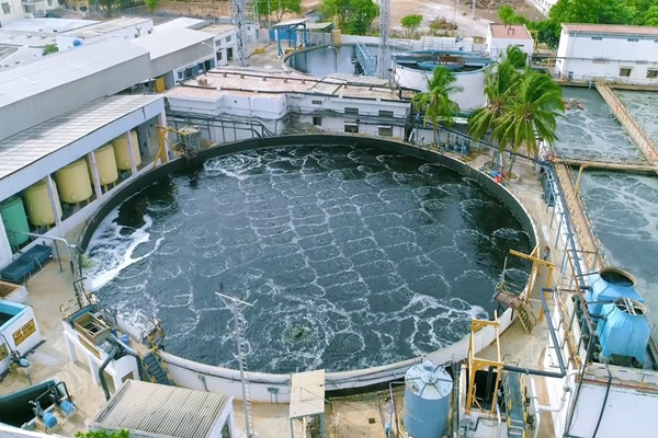
4. Biological oxidation
Subsequently, the neutralized effluent is transferred to the biological oxidation tank, where dissolved and suspended organic matter, along with color, is removed through the action of aerobic microorganisms. This process is based on a modified extended aeration activated sludge system, in which organic load, inorganic suspended solids, and part of the dissolved solids are oxidized. The microorganisms metabolize organic matter, reproduce rapidly, and form colonies known as flocs. Oxygen is supplied through air blowers and fine bubble membrane disc diffusers to support microbial activity. The process results in the formation of water, carbon dioxide, and new biomass. A dissolved oxygen meter is installed to continuously monitor oxygen levels in the tank.
-
5. Sludge flocks have two characteristics
- Settle in gravity
- Have high concentration of active organic matter
The homogenized effluent is fed with air through an aeration system consisting of fine bubble membrane disc diffusers, with relevant headers, manifolds and accessories, placed on the bottom of the tank and producing fine bubbles and air compressor station.An oxygen meter is provided for the monitoring of the O2 concentration in the water. -
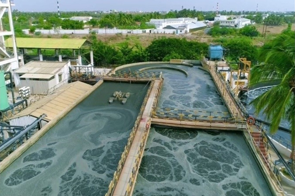
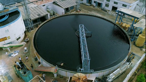
6. Clarifier
The clarifier receives the mixed liquor from the biological oxidation tank by gravity, where the sludge settled down and the supernatant water flows to the treated water storage tank. The mechanical scraper, known as clarifier mechanism is provided at the bottom of the tank and it clarifies the sludge and pushes it to the central collection pit and then it is drawn out finally.
The sludge is recycled back to the aeration tank to maintain the balance between the microorganisms and organic matter from the wastewater. The excess sludge is drained to the sludge thickener, where the sludge is further thickened the supernatant from the sludge thickener over flows to the storage and homogenization tank and removed in to sludge thickener. The sludge recirculation pumps are provided for withdrawing the sludge from the clarifier.
-
7. Filter pressThe thickened sludge from the sludge thickener pumped to the filter press, dewatering poly electrolyte is fed with the sludge to increase the concentration and flock formation. Where the sludge got compressed and removed in the form of sludge cakes. The filtrate from the filter press return back to the biological oxidation tank. The sludge cakes are collected after dewatering and stored under roofed storage yard.
-
8. Gas ChlorinationThe Treated secondary Clarifier outlet is fed to the Gas Chlorination system where the raw chlorine gas is being dosed for the removal of excess colour and odour. The colour reduced effluent is pumped to the Quartz Filters. The residual chlorine is removed by addition of Sodium Meta Bi Sulphate ( SMBS).
-
9. Quartz filtrationQuartz filters are filled with fine and coarse quartz sand and working principle is same like as the pressure sand filter and required for the frequent back wash according to the filtrate quality. The suspended solids and turbidity reduced by passing the effluent through quartz filters. The filtrate from the quartz filter is stored in quartz filtered water storage tank (QFWST). Back washing is done by the filtrate water with air scouring. The back wash discharge taken back to the SHT and recycled back to the system.
-
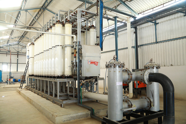
10. The Ultra Filtration
UF Installations at Kasipalayam CETP
To maintain low turbidity and control suspended particles for consistent RO performance, three UF systems have been installed:
4.4 MLD Ultra Filtration - Installed at Softener inlet for stable performance of Resin & RO.
Turbidity - 99.99 % removed (output Turbidity - < 1 NTU) TSS - 99.99 % removed (output TSS - < 1 mg/ L)
-
11. Softening unitSofter filters are installed to reduce the total hardness of the treated effluent from 150mg/l to 10mg/L. The filters are filled with special type of weak acid cation with higher exchange capacity. The softening system is used to protect the RO membrane from scaling. Scaling would take place due to the excess concentration of salts beyond the solubility limits that would result in the precipitation of salts on the brine side. In softeners the calcium and magnesium hardness are reduced, which will prevent the saturation of the salts in the RO rejects. The regeneration of the softener resins are using hydrochloric acid. The wastewater generated from the regeneration process will be fed to the reactor clarifier for further treatment. The filtrate from the softener filter is collected and stored in Softened water storage tank (SWST).